
Main-Switchgear Energy Conditioning
Introducing the C3 EIQ.
One factory-built system, landed at the main switchgear on a single disconnect. It clamps every surge behind the service, corrects the power the facility draws, and meters the result — verified against your own bill, not a brochure estimate.
300 kA surge protection per phase
0.98 power factor design point
Field-verified, not just modeled
or call (800) 222-1440

300 kA
surge capacity per phase, 7 redundant fused paths
1,122 V
delivered at the bus on a 10 kA event
0.98
efficiency factor design point
8–12%
typical savings, all in, of the bill
Get started
Tell us about your service and a recent bill, and we’ll size the right system.
A voltage, an amperage, and a bill is all we need to start — we’ll follow up within one business day. No long forms, no obligation.
- Power quality read at your own gear, not a generic estimate
- Recommendation back in 24–48 hrs
- AutoSensing or Fixed, matched to how your load actually moves
- GSA Schedule pricing available
Name
Phone
Organization
Service voltage, amperage, and a recent bill if handy (optional)
or call (800) 222-1440
Why facilities call
Power events show up on the floor. Energy waste shows up on the bill.
Most facilities come to Power Conditioning for one reason or the other. One machine at the service entrance answers both, at the same time, on the same disconnect.
Power Events
An event shows up on the floor
A blip reads as scrap on the line, a process restarted, a drive or control board replaced early, and a shift spent bringing the facility back. The C3 EIQ clamps every event at the main in four modes, counts it, and shows the count through the door window.
Surges and spikes — 300 kA per phase on 7 redundant fused paths. Equipment behind the service sees 1,122 V on a 10 kA event.
Sags and flicker — Reactive current supplied at the gear stands the bus up; one facility’s own record took 59 undervoltage events to 7.
Swells — Varistors rated 346 V on a 277 V system, 24.9 percent headroom, carry the stage through a long-duration swell.
Energy Savings
The savings show on the bill
Correction at the main takes reactive current out of the utility transformer, the service conductors and the meter. Current falls, the heat and losses carried by that current fall with its square, and billed demand comes down.
Typically 8 to 12 percent, all in — measured on the facility’s own bill, with demand metered as its own line inside the figure.
15.82 percent less current — in a worked 3,553 kW service at 480 V, moved from 0.825 to 0.98. Resistive loss on that current fell 29.13 percent.
Confirmed in the field — a computed 8.16 percent current and 15.66 percent loss reduction was met by a measured 8.00 and 15.03.
Where it lands
One connection, at the main switchgear.
The C3 EIQ lands at the service entrance, on the main switchboard or switchgear fed from the utility transformer, ahead of the distribution — not tucked at a subpanel downstream. Every amp the facility receives passes that point, so one machine conditions the whole service and everything it feeds. It is shunt-connected, parallel to the bus and clear of the path of the load.
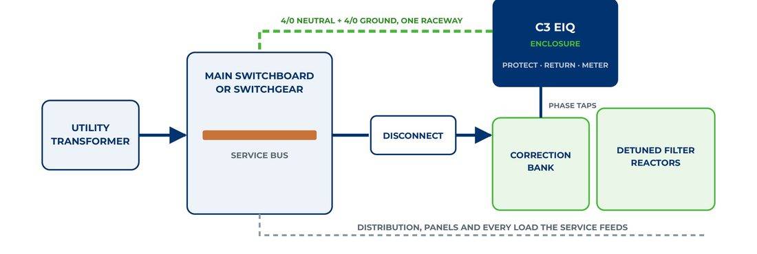
Five stages, one enclosure, one disconnect
| Stage | What it is | What it sets |
| 01 Correction | A capacitor bank on heavy-duty cells built for a twenty-five-year life, switched by AutoSensing or held as a fixed stage | Reactive current supplied at the gear, so the transformer and service conductors stop carrying it |
| 02 Filter reactors | Detuned filter reactors applied as the audit requires, sized to the service and tuned to impact the dominant harmonic orders | The bank held out of resonance and a share of the fifth harmonic drawn into the branch |
| 03 Return path | Insulated neutral bar, with a 4/0 copper neutral bundled with a 4/0 copper ground back to the main | 137 V per foot on the way out, against 583 V for the same pair run apart |
| 04 Protection | 300 kA per phase of MOV protection, 7 redundant paths per phase, each with its own fuse and thermal disconnect | 1,122 V delivered at the bus bar on a 10 kA event |
| 05 Measurement | A revenue-grade Class 0.2 meter in the door, reading the whole service through sensors at the main | The record: power factor, power, current, voltage, distortion, energy and the surge event count |
Two forms, one system
Matched to how your load actually moves.
Same enclosure, same protection, return path and metering on every unit. The correction stage is the one part built to your facility: a switched bank that follows the load through the day, or one fixed stage sized to hold through the lightest hour.
AutoSensing Energy Intelligence
It senses the load and adjusts to it.
A switched correction bank and its controller, set to hold the 0.98 to 0.99 lagging design point as the facility’s load moves through the day. The controller reads the reactive requirement interval by interval and calls exactly the stages the load needs, rotating the cell groups — an hour on 1 2 3 4, then 5 6 7 8, then 1 3 5 7 — so wear spreads across every cell. A transfer switch contact releases the bank when a generator takes load and re-enables it on return; protection, return path and metering stay in circuit throughout.
Design Point
0.98–0.99 lagging, held through the day
Best Fit
Load that moves — shifts, seasons, production swings

Fixed Energy Conditioner
One fixed stage, sized to hold every hour.
One fixed correction stage, sized on the facility’s lightest measured reactive demand from its own metered record, so the bus holds lagging through nights, weekends and light shifts — not just the peak. Built for steady, around-the-clock loads: continuous process, cold storage, pumping and lines that carry a reactive floor every hour. The same protection, return path and metering as every C3 EIQ, with the step up to AutoSensing available if the audit later shows the load moving through the day.
Design Point
0.98 lagging, held at every hour
Best Fit
Steady, around-the-clock load with little daily swing
The protection stage
300 kA per phase. 1,122 V at the bus.
A single lightning flash is 2 to 20 separate strokes. Seven fused paths per phase conduct together, so the stage carries the whole flash and stays in service through it — the same path count on a 400 ampere service as on a 3,000 ampere service.
7
redundant paths per phase, each with its own fuse and thermal disconnect
24
fused paths installed on a wye service
<5 ns
response, conducting on the rising front
Lifetime
replacement of the MOV inserts at no charge
Every equipment class, with margin
| Spec | Withstand | C3 EIQ | Margin |
|---|---|---|---|
| I, electronics | 1,500 V | 1,122 V | 25% |
| II, equipment | 2,500 V | 1,122 V | 55% |
| III, distribution | 4,000 V | 1,122 V | 72% |
| IV, service entrance | 6,000 V | 1,122 V | 81% |
Return path, at 10 kA
| Spec | Volts per foot |
|---|---|
| 4/0 neutral bundled with its 4/0 ground | 137 |
| 1/4 by 2 inch copper bar in the enclosure | 222 |
| #10 round lead over the same run | 412 |
| Same 4/0 pair routed 12 inches apart | 583 |
Type 2 SPD, UL 1449 5th Edition Listed. In 20 kA, SCCR 100 kA. Surge life 10,000 events at 13 kA per phase. EMI and RFI filtering, 30 to 60 dB across 50 to 190 kHz. Form C status contact to the facility system.
Inside the C3 EIQ
Open the door. Everything is built in the shop.
Bench built and bench tested in a UL 508A registered panel shop, audited unannounced every quarter. The four-inch protection path, the two-hole terminations and the torque schedule are set on the bench and are the same on every unit.
- Three 1/4 by 2 inch copper phase bars, one node for protection, correction tap and metering
- Its own listed protection housing, 24 fused paths, status and counter behind the window
- Insulated neutral on two-hole pads, bonded at one point so the single service bond stays intact
- Class 0.2 meter in the door, reading the whole service while the door stays shut
- 48 by 36 by 12 inches, 14 gauge painted steel, three hinges, one-motion door
- UL 508A listed industrial control panel, approved across 240, 480 and 600 volts

Proven on the record, not just modeled
Predict. Install. Meter. Prove.
Every candidate size is run against the facility’s own metered record before the order goes in — not a generic table lookup. The method has been run and rerun across two dozen facility records, retested at every change, and the field has matched it.
On-off record, seven matched load bins
−10.79%
current
−19.96%
resistive loss
+2.10 V
at the bus
The pre-order model on that same record projected 11.92, 22.42 and 1.44 V — the measured bus lift ran a third higher than the model predicted.
Measured against computed
8.00% / 8.16%
current measured against modeled
15.03% / 15.66%
resistive loss measured against modeled
The starting efficiency factor sets the story
| Spec | Efficiency Factor | What the Record Shows |
|---|---|---|
| Cold rolling mill | 0.643 | 29.1% less current, 11.60% all in |
| Heat treating | 0.728 | 25.9% less current, 9.59% all in |
| Packaging and compaction | 0.940 | 833 load steps a day, 304,260 a year |
| Water treatment | 0.957 | 30.3% current distortion |
Verification is metered ON/OFF testing at the gear under IPMVP Option B, with a timestamped surge event record and live readings at the unit and to the facility’s own system. Every facility is different, so the run is made on yours — not a catalog default.
Built and covered
Built in America. Documented for federal buyers.
Every principal stage is designed, built and assembled in the United States, with every component listed by a nationally recognized testing laboratory. For a public-safety, utility, or government buyer that has to document compliance, not just claim it, the paperwork is already built into the order.
Buy American Act
Met in every configuration, FAR 25.101
Build America, Buy America
Met in every configuration, 2 CFR 184.3
Trade Agreements Act
Met directly by domestic manufacture
DFARS & Section 889
Domestic end product, no covered telecommunications equipment
80%+
domestic content, base enclosure
84%+
domestic content, fixed correction system
92%+
domestic content, filtered correction system
A domestic content package letter is prepared against your named project at order. A power quality survey of your gear is read against your own billing record before it’s built.
Service life and coverage
Covered for the long run.
5 yr
on all C3 EIQ components, from commissioning
20 yr
on the surge protective device
Lifetime
replacement of the MOV inserts, at no charge
25 yr
product life, serviced in place from the front
Every wearing item is reached from the front with the door open. An MOV insert changes in five to ten minutes behind a three thumb-screw barrier, so the facility carries no planned maintenance budget for the unit.
Side by side
AutoSensing and Fixed, compared.
| Spec | AutoSensing | Fixed |
|---|---|---|
| Correction | Switched bank and controller, stages called interval by interval | One fixed stage, sized on the lightest measured hour |
| Design point | 0.98–0.99 lagging, held through the day | 0.98 lagging, held at every hour |
| Cells | Heavy-duty capacitor cells, 25-year life, groups rotated for even wear | Heavy-duty capacitor cells, 25-year life |
| Best fit | Load that moves through the day — shifts, seasons, production swings | Steady, around-the-clock load with little daily swing |
| Filter reactors | Detuned, applied as the audit requires | Detuned, applied as the audit requires |
| Protection | 300 kA per phase at the main, 7 redundant fused paths | 300 kA per phase at the main, 7 redundant fused paths |
| Return path | Insulated neutral, 4/0 neutral bundled with 4/0 ground | Insulated neutral, 4/0 neutral bundled with 4/0 ground |
| Measurement | Class 0.2 meter in the door, surge event counter, Form C contact | Class 0.2 meter in the door, surge event counter, Form C contact |
| Enclosure | 48 by 36 by 12 inches, 14 gauge painted steel, UL 508A listed | 48 by 36 by 12 inches, 14 gauge painted steel, UL 508A listed |
| Generator transfer | Transfer switch contact releases the bank on generator, re-enables on return | Protection, return path and metering stay in circuit throughout |
| Coverage | 5 yr components, 20 yr SPD, lifetime MOV replacement, 25 yr product life | 5 yr components, 20 yr SPD, lifetime MOV replacement, 25 yr product life |
Both forms are sized against your facility’s own metered record before the order, and both ship as one factory-built system on one disconnect. Product weight, exact dimensions by service voltage, and warranty terms by configuration are confirmed at quote against your named project.
Installed and operating: facility power conditioning systems built on this platform are in service across manufacturing, packaging and infrastructure sites nationwide, including installations at sites for Johnson Controls, Owens Corning and Dura-Line. References shared on request.
Common questions
Power conditioning FAQs.
Should I choose AutoSensing or Fixed?
If the audit shows your load moving meaningfully through the day — shift changes, seasonal swings, production ramps — AutoSensing’s switched bank follows it. If your load carries a steady reactive floor around the clock, Fixed is sized once on your lightest measured hour and holds it. We size this from your own metered record, not a guess.
How is the savings number actually produced?
Every candidate size is run against your facility’s own metered record before the order, and after commissioning the result is verified by metered ON/OFF testing under IPMVP Option B — a documented measurement and verification protocol, not a brochure percentage.
Does it need a special room or cooling?
No. The enclosure is a standard 48 by 36 by 12 inch NEMA-rated panel that lands at your existing main switchgear or switchboard. It requires no dedicated cooling or conditioned environment.
What happens on generator power?
A transfer switch contact releases the correction bank when the generator takes load and re-enables it after a stabilizing delay on return. Protection, the return path and metering all stay in circuit through the run.
What if it takes a direct lightning or surge event?
The protection stage carries 7 redundant fused paths per phase, each with its own fuse and thermal disconnect, so an individual path failing doesn’t take the stage out of service. MOV inserts are field-replaceable in five to ten minutes and are covered for lifetime replacement at no charge.
Does this replace our UPS or backup power?
No — the C3 EIQ conditions and corrects the power the facility draws and protects against surges; it doesn’t provide backup runtime during an outage. See Critical Power & Cooling for UPS and generator-side solutions, which pair naturally with a main-switchgear conditioner.
See what’s actually on your own bill.
A voltage, an amperage and a recent bill is all it takes to start — we read your gear and compute the result on your own numbers, not a catalog estimate.